GB24_Antennas characterization
Antenna characterization
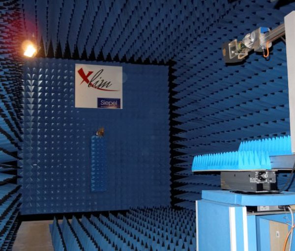
The objective of an antenna test range is to simulate the operational environment of the test antenna so the radiation specifications would be measured in a way as realistic as possible. The distance R between the antenna under test and the transmit antenna is great enough to approximate the spherical wave by a plane wave. The conventional far-field condition must respect this relation R = 2D2/λ with D the maximum aperture diameter and λ the wavelength
|
|
 |
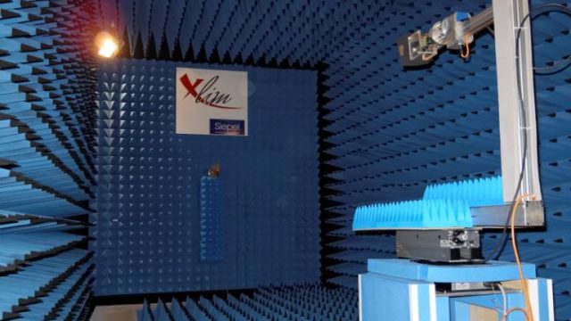
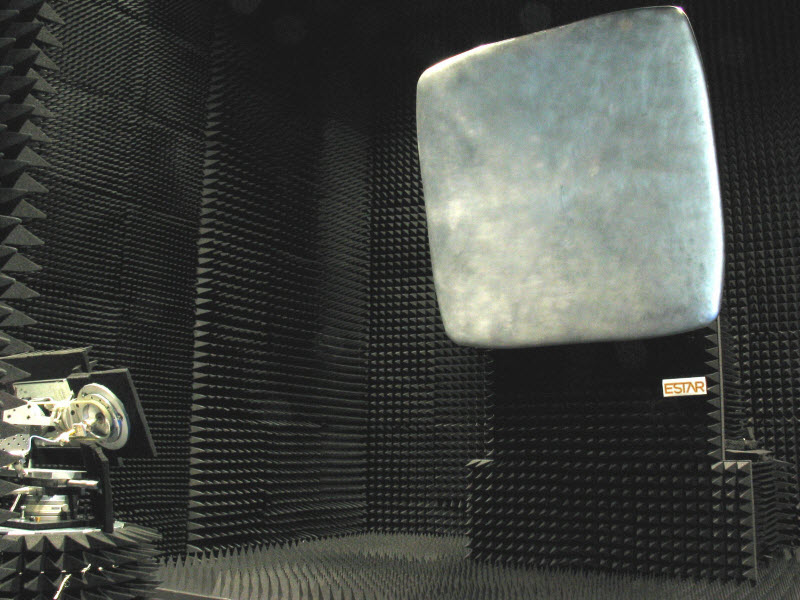
View of the indoor antenna test room
Features :Frequency Range: 0.5 GHz to 12.0 GHz Full anechoic and shielded chamber External dimensions: 9 m x 5 m x 5 m Antenna size limits :1 m to 500 MHz and 0.3 m to 12 GHz Weight limits: 20 Kg |
Feasible measurement:Matching impedance (|S11|) Radiation pattern (0.5°) Polarization radiation pattern Realized gain (± 0.5 dB accuracy) Directivity (accuracy of gain) |
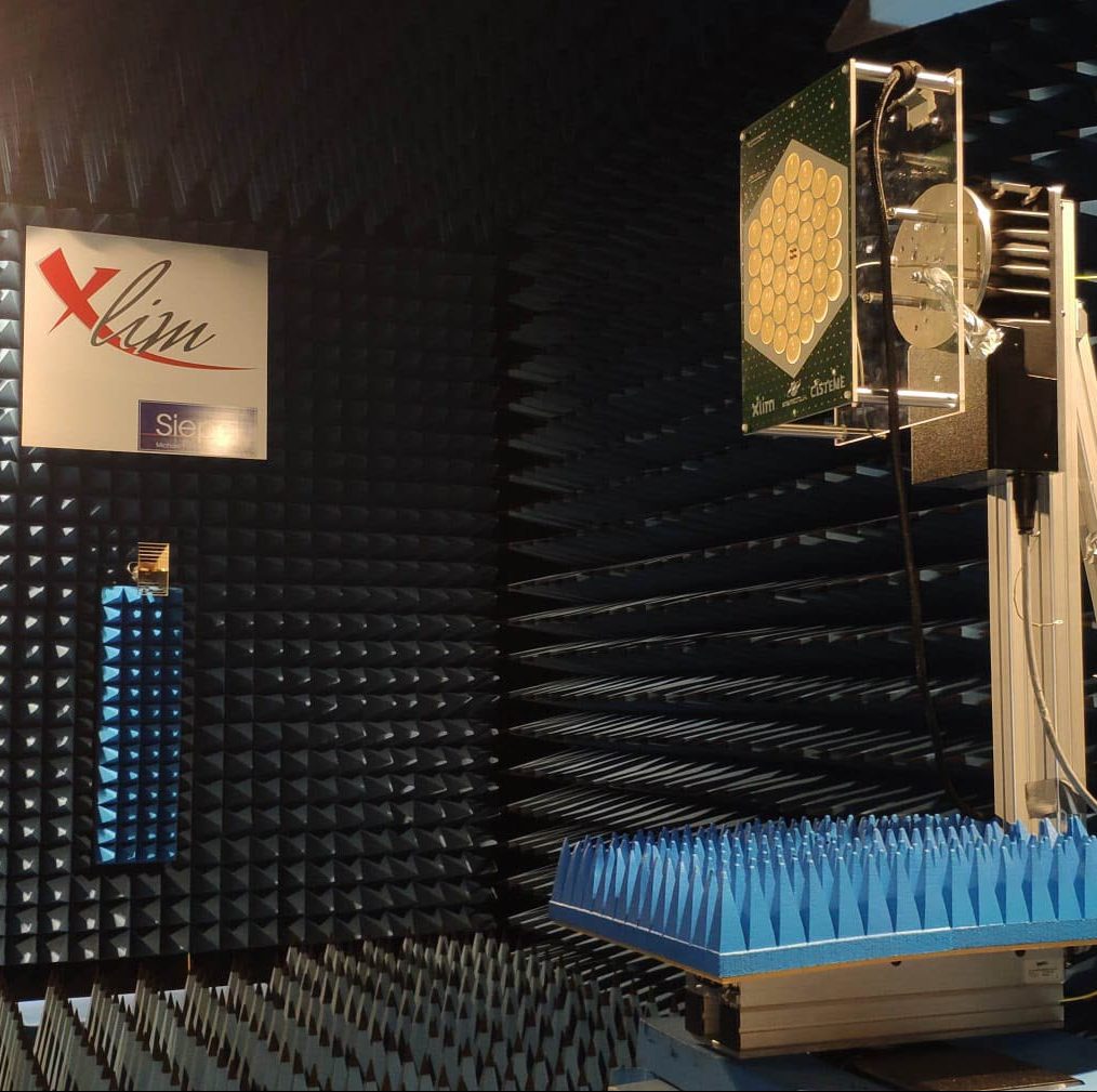
Compact Antenna Test Range (PLATINOM/CISTEME)
CATR provides a far-field condition at a relatively short distance from the feed. The principle is to produce a quasi-plane wave test region by collimating the field from a point source using a equiphase radiating aperture such as a parabolic reflector.
|
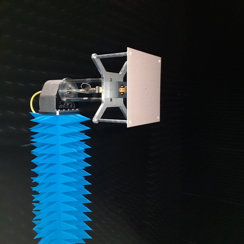 |
Views of the compact base and reflector
Characteristics:Frequency Range: 8.0 GHz to 110 GHz Full anechoic and shielded chamber External dimensions: 8 m x 5 m x 5 m Antenna size limits :80 cm Weight limits: 6 Kg |
Feasible measurement:Matching impedance (|S11|) Radiation pattern (0.5°) Polarization radiation pattern Realized gain (± 0.5 dB accuracy) Directivity (accuracy of gain) |
XLIM - Faculté des Sciences et Techniques
87060 LIMOGES CEDEX