java -version

My name is Frédéric Claux. I am Associate Professor at the University of Limoges.
Visit my research page for more details on my research.
See the teaching page or the Master ISICG programme of the Faculty of Sciences for more details on teaching.
Here is my quick resume:
-
Since 09/2015: XLIM, University of Limoges, Faculty of Sciences
-
2014-2015: INRIA Nancy, ALICE team.
-
2009-2013: IRIT, PhD candidate.
-
2005-2009: Microsoft Corporation, Redmond, WA, USA. Virtual Earth Team. Working on Map Rendering.
-
2004-2005: Navman New Zealand Ltd, Auckland, New Zealand. Map Core Engineering Team (GPS devices). Working on Map Rendering (lead developer).
-
2001-2003: Techbase, Paris, France. GIS engineering. Lead developer.
-
1999-2001: Geotech, Paris, France. GIS engineering.

Email address:
frederic.claux AT unilim.fr
Postal address:
Frédéric Claux
Université de Limoges
XLIM UMR CNRS 7252
123, avenue Albert Thomas
87060 Limoges Cedex
News
Dense, deep learning-based intracranial aneurysm detection on TOF MRI using two-stage regularized U-Net
March 22, 2022
Frédéric Clauxa,1, Maxime Baudouinb,1, Clément Bogeyb, Aymeric Rouchauda,b
Journal of Neuroradiology, 2022
1 FC and MB are co first authors.
a University of Limoges, CNRS, XLIM
b Limoges University Hospital (CHU Dupuytren), Department of radiology
Paper available here.

Background and purpose
The prevalence of unruptured intracranial aneurysms in the general population is high and aneurysms are usually asymptomatic. Their diagnosis is often fortuitous on MRI and might be difficult and time consuming for the radiologist. The purpose of this study was to develop a deep learning neural network tool for automated segmentation of intracranial arteries and automated detection of intracranial aneurysms from 3D time-of-flight magnetic resonance angiography (TOF-MRA).
Materials and methods
3D TOF-MRA with aneurysms were retrospectively extracted. All were confirmed with angiography. The data were divided into two sets: a training set of 24 examinations and a test set of 25 examinations. Manual annotations of intracranial blood vessels and aneurysms were performed by neuroradiologists. A double convolutional neuronal network based on the U-Net architecture with regularization was used to increase performance despite a small amount of training data. The performance was evaluated for the test set. Subgroup analyses according to size and location of aneurysms were performed.
Results
The average processing time was 15 min. Overall, the sensitivity and the positive predictive value of the proposed algorithm were 78% (21 of 27; 95% CI: 62–94) and 62% (21 of 34; 95%CI: 46–78) respectively, with 0.5 FP/case. Despite gradual improvement in sensitivity regarding aneurysm size, there was no significant difference of sensitivity detection between subgroups of size and location.
Conclusions
This developed tool based on a double CNN with regularization trained with small dataset, enables accurate intracranial arteries segmentation as well as effective aneurysm detection on 3D TOF MRA.
AneuDetect: deep, variational aneurysm detection tool
The tool is available for download here.

Installation requirements
The detection tool has the following requirements:
-
Hardware requirements
-
16GB of RAM (24GB of RAM recommended), 6GB of on-board graphics card RAM for predictions
-
32GB of RAM, 12GB of on-board graphics card RAM for training (8GB should be enough if half-precision training is used)
-
nVidia graphics card of generation 7xx or later with the required amount of memory (eg. 980Ti+, 1070+, 16xx, 20x0, 30x0 and all existing Titan cards)
-
-
Software requirements
-
Windows 7, 8, 10 or 11 (64 bits only)
-
Java >= 11. Java JDK can be downloaded from here.
-
recent nVidia graphics driver, supporting at least CUDA 11.2 (see below)
-
CUDA >= 11.2. CUDA can be downloaded from here.
-
cuDNN >= 8.1. cuDNN can be downloaded from here. cuDNN files need to be manually copied over to the CUDA folders.
The installation procedure of cuDNN files into CUDA directories is described here. There is a minor error in this page, whereby files should not be copied to 'C:\Program Files\NVIDIA\CUDNN\v8.x', but to %CUDA_PATH%:
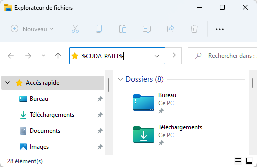
which gives (when ENTER is hit):
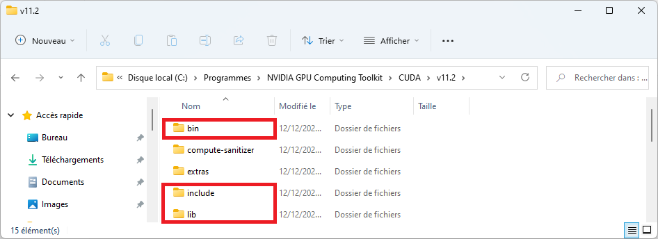
cuDNN files should be copied into the folders highlighted in red, as explained in the installation procedure.
-
The tool has been tested on CUDA 11.2.2 and cuDNN 8.2.
To check your configuration before installing anything:
-
open a command prompt (Win+R then type cmd.exe)
-
type
to see if any Java runtime is currently installed on your system, and to check the version. If the command produces an error, Java is not installed.
-
check the CUDA version supported by your driver by typing
nvidia-smi
Note the CUDA version displayed here is not your installed CUDA version (if any). This command also lists the amount of memory.
-
type
echo %CUDA_PATH%
to check your CUDA installation. If nothing is displayed, this means CUDA is not installed. If a directory path is displayed, the path will give you the version number.
-
type
dir "%CUDA_PATH%\bin\cudnn*"
to list files starting with "cudnn" in the CUDA folder. If you don’t see any file, this means cuDNN has not properly been installed.
Installation procedure
Just unzip the archive in a folder and double-click on the file with the .JAR extension.
Using the tool
Power-saving is automatically disabled while a prediction or a training operation is in progress.
The tool does not check the validity of input files or parameters. If any file provided is incorrect, or in an unsupported format, or if parameter values are bogus, the behavior of the tool will be unpredictable or the tool may just crash.
Importing MRI data
Expected directory structure and file format
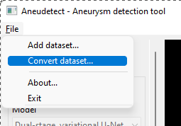
The tool needs to convert input files into its own format before predictions or training can take place. The conversion procedure is mainly meant to accelerate training, but is also required for predictions. The File > Convert dataset menu item can be used to import data, in Nifti format (.nii.gz) only. Note that Nifti files must contain voxel size information. A folder should be selected. This folder should contain subfolders in which TOF data may be found, with or without additional segmentation data. There should be
-
one folder per MRI
-
if only one file is present in the folder, this file will be treated as the TOF MRI.
-
if two files are present in the folder, the second one should use the same name as the first one, appended with an 'S'. This file is treated as a radiologist’s segmentation (ground truth) of a TOF MRI and may be used for training. Aneurysms should be marked with a value of 2, vessels 1, and background 0.
For instance, you may have a folder P10000 containing two files, P10000.nii.gz and P10000S.nii.gz. P10000.nii.gz is the TOF and P10000S.nii.gz is the corresponding manual segmentation.
Detailed import procedure
These screen captures detail the import procedure.
-
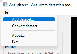
Select the File > Convert dataset… menu item
-
Select the top-level dataset folder, the one containing one subfolder per MRI. Each subfolder contains one or two .nii.gz files.
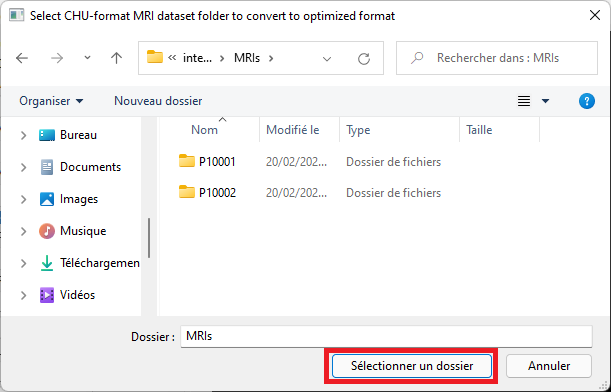
-
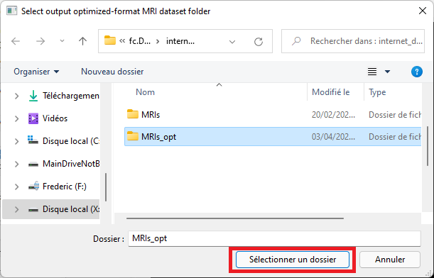
Select an empty output folder where to save converted data. This folder will later be used to perform predictions, or for training.
A conversion dialog will appear and the import procedure will take place. Please wait until the procedure has completed. Note that estimated time may be incorrect in this dialog and can be ignored.
Predictions
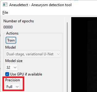
The application ships with a pre-trained model with a size of 64, with a reference voxel size of 0.4 mm. Select or enter the correct model and voxel sizes, click the 'Restore model' button and select the 'weights' folder containing model weights, as illustrated below.
-
Select the 'Add dataset' menu item
-
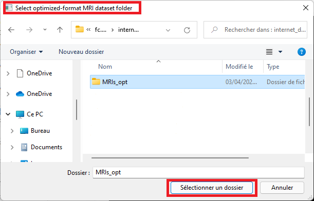
Select the folder that contains files in optimized format (see the conversion procedure in the section above)
-
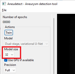
Select the model size. This size must match the size of the model for which weights have been saved (a dialog will pop up and complain otherwise) The proposed, saved model has a size of 64 (note the default size is 32 only).
-
Select the prediction precision. If your GPU has less than 8GB of on-board memory, you may have to select 'Half' precision instead of 'Full'. Prediction quality will only be marginally impacted.
-
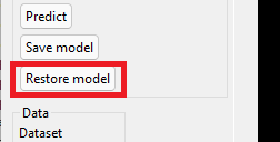
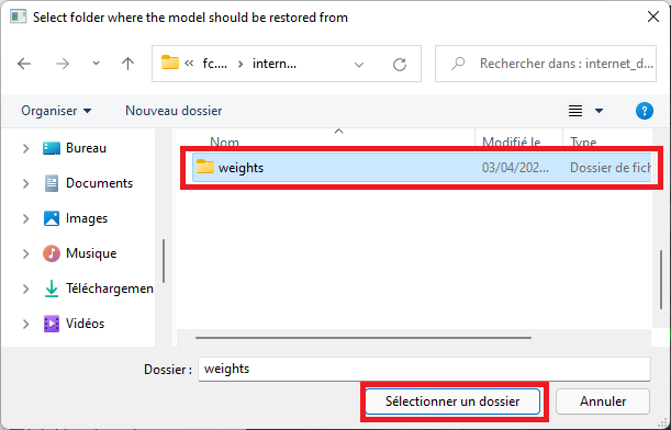
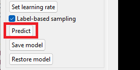
Click the 'Restore model' button.
-
Select the 'weights' folder
-
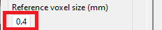
Make sure the voxel size used for predictions matches the voxel size of the saved model. The proposed model was trained with a reference voxel size of 0.4 mm (default value).
-
Click the 'Predict' button to detect vessels and aneurysms for the currently displayed MRI. Prediction time depends on your setup.
-
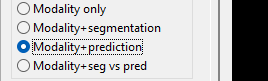
Once the prediction is complete, make sure you select 'Modality+prediction' in the view settings.
Note you may use the 'Batch predict' button to calculate predictions for all MRIs in the current dataset. This may take a while though, be prepared to wait. The tool will automatically prevent the computer from entering power saving while predictions are in progress.
Training
You can perform your own training by clicking the 'Training' button. Choose a model size, a regularization power and a learning rate, in that order. Default values should be preferred although the model size should be increased to at least 64. Training a model with size 32 may be done on low-memory computers (eg. 4GB graphics card). Half-precision mode should be used when graphics card memory is low (less than 8GB). Save the model with 'Save model' after training. Model weights may be loaded back later on.
Enseignements à venir
April 13, 2020
Mise à jour des enseignements dans le Master ISICG
Le Master ISICG modernise ses cours, pour y adjoindre davantage d’I.A., et notamment de deep learning appliqué à l’image et aux formes géométriques.
Les cours vont aborder davantage d’applicatifs tels que la vision par ordinateur, et la synthèse d’images et de formes par l’exemple.
Plus d’informations ici.
Stage M2: capture de la géométrie d'un jeu OpenGL
April 07, 2020
Capture de la géométrie d’un jeu OpenGL par instrumentation des shaders OpenGL
Ce stage de Master 2 de Bastien Thomasson a porté sur la capture de la géométrie d’un niveau de jeu et ce, au fur et à mesure que l’on joue. Le travail portait sur l’écriture d’un programme permettant :
-
d’intercepter les appels OpenGL pour les dérouter vers des fonctions d’analyse et de capture. Cette fonctionnalité fait essentiellement appel à de la programmation système.
-
d’instrumenter les shaders pour capturer les informations géométriques. Cette fonctionnalité fait appel à l’analyse grammaticale (bison, flex ; nous avons aussi testé du code ANTLR)
-
de reconstituer un univers 3D en inférant la matrice de transformation globale à partir de la matrice de vue, image après image.
-
capture automatique une fois un paramétrage mis en place pendant que le jeu tourne, effectué une seule fois. Et ce, sans altérer le fonctionnement du jeu.
-
programmation de toute l’interface utilisateur nécessaire à cet effet
Un nuage de points est ainsi alimenté au fur et à mesure que le joueur évolue dans son environnement. Nous nous sommes arrêtés là, mais un maillage peut être reconstitué très rapidement avec des méthodes comme Raster2Mesh (video).
Nous avons testé la capture avec deux jeux, IOQuake 3 (dans la vidéo), et SuperTuxCart.
Les appels OpenGL sont d’abord détournés. Sous Windows, cela consiste à appeler CreateProcess(), attendre le chargement des bibliothèques OpenGL (OPENGL32.DLL et éventuellement les bibliothèques spécifiques aux drivers, fonctions récupérables par wglGetProcAddress()), à récupérer les adresses, puis à poker dans l’espace virtuel du process via WriteProcessMemory() pour détourner vers des fonctions typiquement chargées dans une DLL contenant l’implémentation des fonctions détournées. Ces dernières font leur travail puis appellent à leur tour les vraies fonctions OpenGL.
Il existe d’autres manières de détourner des appels, comme par exemple :
-
la bibliothèque Detours, de Microsoft Research, qui suit des principes semblables à ceux décrits ci-dessus.
-
pour les objets COM, la fonction CoTreatAsClass(), ou l’Universal Delegator. Ce dernier permet de faire de l’aggrégation d’objets après que les objets aient été créés (à l’instar de COM_INTERFACE_ENTRY_AGGREGATE_BLIND, mais au moment de l’exécution).
Le programme repose sur l’instrumentation de shaders, dont l’analyse est illustrée de manière basique dans la vidéo ci-dessous.
3D printing of a face mask during lockdown
April 06, 2020
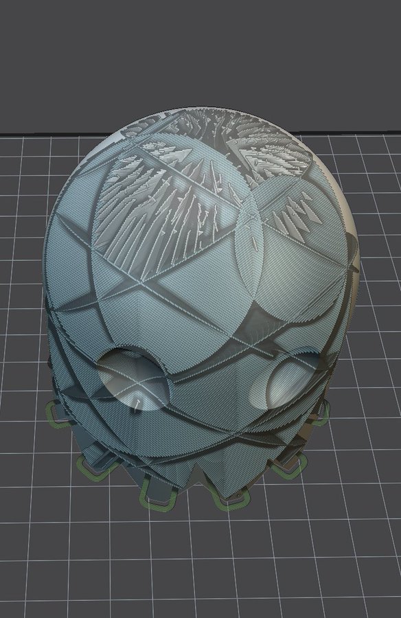
3D printing of a face mask. I am sending here the GCode that was built to slice the face mask, in STL form. This is done by my own software application that I use for the Master ISICG 3D printing course. The printing process itself takes place on a Printrbot Simple Metal 3D printer. This printer is discontinued but still used for some courses at the University. Note that this mask is built for educational purposes only. Its effectiveness is weak compared to FF2 masks bought in pharmacies.
The fitting of the mask is not bad for adults but is obviously inappropriate for kids (I’ve seen other masks that are more suitable).


3D print of the support grid:
Ribbed support vaults for 3D printing of hollowed objects
June 21, 2019
Thibault Tricard, Frédéric Claux, Sylvain Lefebvre
Computer Graphics Forum, 2019
Additive manufacturing techniques form an object by accumulating layers of material on top of one another. Each layer has to be supported by the one below for the fabrication process to succeed. To reduce print time and material usage, especially in the context of prototyping, it is often desirable to fabricate hollow objects. This exacerbates the requirement of support between consecutive layers: standard hollowing produces surfaces in overhang that cannot be directly fabricated anymore. Therefore, these surfaces require internal support structures. These are similar to external supports for overhangs, with the key difference that internal supports remain invisible within the object after fabrication. A fundamental challenge is to generate structures that provide a dense support while using little material. In this paper, we propose a novel type of support inspired by rib structures. Our approach guarantees that any point in a layer is supported by a point below, within a given threshold distance. Despite providing strong guarantees for printability, our supports remain lightweight and reliable to print. We propose a greedy support generation algorithm that creates compact hierarchies of rib-like walls. The walls are progressively eroded away and straightened, eventually merging with the interior object walls. We demonstrate our technique on a variety of models and provide performance figures in the context of Fused Filament Fabrication (FFF) 3D printing.
Paper available on HAL
Below is a link to a Windows binary (64 bits) that can be used to generate the supports.
Authors: Frédéric Claux and Thibault Tricard
Requirements: a 64-bit Java 8 or later Virtual Machine needs to be installed on your computer. If both a 32-bit and a 64-bit JVM are installed on your computer, the 64-bit JVM must be the default JVM. The application also requires an OpenGL 4.3 graphics card and a recent graphics driver. Any graphics card manufactured after 2010 should work. You must agree with the terms listed in the About dialog prior to using the application for support generation.
Our method is covered in a 3dprint.com article


Cura
A derived version of our algorithm, named 'lightning infill', is proposed in the latest Ultimaker Cura software (4.12), download Cura here.
Our work is featured in Lost in Tech’s "Lightning infill is new in Cura. But what on earth is it?", as shown below.
External supports for PVA
Our method can be used for external supports when using PVA material. PVA is a soluble material that can be dissolved in water. Using PVA for external supports on dual-filament printers is a good way of improving the quality of printed objects. Hand-removable external supports leave defects on printed parts, and using PVA usually alleviates this problem. Printing with our method significantly accelerates the printing process, without hampering final print quality.


One difficulty I needed to address in our method was a problem with the extrusion.
Our method uses a large amount of printed paths of small lengths, potentially causing oozing when retracts and primes are not being used, essentially when the travel distance between support segments is really small. When a lot of oozing takes place, filament stringing can be observed and under-extrusion subsequently follows.
This was not the only problem though. I also observed on two entry-level 3D printers that for travel paths that did trigger retracts and primes - and these can be numerous - the very large amount of retracts and primes caused a small error on the extrusion axis, usually in a defavorable way wrt. the quantity of plastic being pushed down, also resulting in under-extrusion. We thought at some point that the dented wheel was eating away the filament, but observations did not confirm that. Instead, I believe the filament just moves a tiny bit and has a hard time to be primed back into its exact, original position, resulting in a tiny but effective shortfall.
These issues are shown in the picture below.
The various cubes that have been printed here show perimeters affected by the phenomenom of under-extrusion. Fortunately, slightly over-extruding when doing primes was an easy enough fix, especially since print support quality doesn’t need to be perfect. In the end, it just took some time to make sure we fully understood the problem to be sure to provide an appropriate fix.

New EGSR 2019 paper!
June 20, 2019
Our paper Glint Rendering based on a Multiple-Scattering Patch BRDF has been accepted at EGSR 2019 (CGF track).
Check out the paper page for paper details, submission video and full source code!
HCSG: Hashing for real-time CSG modeling
August 01, 2018
Cédric Zanni, Frédéric Claux and Sylvain Lefebvre
ACM on Computer Graphics and Interactive Techniques, July 2018
Constructive Solid Geometry models solids as boolean combinations of base primitives. It is one of the classical modeling approaches in Computer Graphics. With the advent of 3D printing, it has received a renewed interest: CSG affords for the robust definition of solids, and fits well with parametric modeling, affording for easy customization of existing designs.
However, the interactive display and manipulation of CSG models is challenging: Ideally, CSG has to be performed between a variety of solid representations (meshes, implicit solids, voxels) and the renderer has to provide immediate feedback during parameter exploration. The end result has to be prepared for fabrication, which involves robustly extracting cross-sections of the model.
In this work we propose a novel screen space technique for the rendering, interactive modeling and direct fabrication of parametric CSG models. It builds upon spatial hashing techniques to efficiently evaluate CSG expressions, checking whether each interval along a view ray is solid in constant time, using constant local shader memory. In addition, the scene is rendered progressively, from front to back, bounding memory usage. We describe how the hash encoding the CSG is constructed on the fly during visualization, and analyze performance on a variety of 3d models.
New 3D printing Master option
October 16, 2016
Starting this september we have a new option for our Master 2 ISICG at the University of Limoges.
The option consists of a 30-hour course where the following topics will be addressed:
-
Introduction to 3D printing
-
Slicing
-
Toolpath generation
-
GPU/OpenGL programming for 3D printing
-
A familiarisation with the GCode language used by 3D printers.
-
Throughout the course, students will be programming their own 3D printing application, from start to finish.
Feel free to contact me directly for more information about this new option.


New endeavors
October 15, 2015
New endavors await in the city of Limoges! I have just been hired in the Faculty. Stay tuned!